As promised, here is the 2nd instalment of the update to the revised layout plans we announced here previously on the blog. In this posting we will look at the digital drawings for the reconfigured layout for Level 1 in both Room 1 and Room 2. I will go over the changes and how scheduled trains will operate on each level. The drawings for Level 2, Level 3 and what we’re calling “3.5” and “4” (although not really full “levels” by any stretch) will be posted in the next few blog updates, which will be followed by a summary of scheduled trains on the C&O, CASO and other associated operations.
If you’re thinking of grabbing something cold or hot to drink, you might want to do it now. This isn’t going to be a short posting.
But first – the new drawing for Level 1:
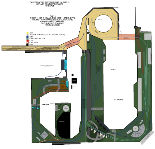
Digital scale drawing for Level 1 (Rooms 1 & 2).
Click for a larger view
Room 1 (right hand side) contains C&O St Thomas Talbot Yard, C&O Kettle Creek Bridge, C&O St Thomas engine facilities, C&O-L&PS/CNR interchange yard, CASO Kettle Creek Bridge, CASO St Thomas station (to scale), CASO St Thomas Yard, both CASO shop buildings (original and 1913 building), CASO transfer table, CASO-CPR Freight Shed (to scale) and a small CPR interchange with the CASO.
Room 2 (left hand side) contains C&O Buffalo/Niagara staging, CASO Buffalo/Niagara staging, CASO Hagersville & Montrose staging, C&O Sub 2 Chatham Yard staging, C&O-CNR Chatham Junction, C&O Chatham Engine facilities, C&O MacGregor Creek bridge, C&O Chatham Station, C&O-CPR Chatham Junction, C&O Colbourne Street Mill Spur, C&O Thames River bridge, RFS engine facilities. Just outside of the room is small staging sidings for “east end” C&O Sub 1 Ridgetown, Muirkirk, Rodney, West Lorne, Dutton and Middlemarch.
Both rooms connect to the helix box from four different directions, two of them using swinging doors in Room 1 and Room 2.
The swinging door that was built in Room 1 for the previous design showed quite clearly that the stable construction made the concept a worry-free one that could be depended upon for smooth operations. When working on drawings for this reconfiguration, I included a new swinging door outside of the doorway entrance to Room 2 for Levels 1, 2 and 3 as I was confident in that design feature now that we had proven the design on our first swinging door was a bullet proof one. In doing so, it freed up all kinds of possibilities for better use of the space in Room 2.
An overview of the new Level 1 design (parenthesis will indicated if a scene is going to be modelled with scenery, structures, etc or will not be modelled and left as simply staging trackage):
ROOM 1
C&O Talbot Yard (modelled scene)
– Some adjustments will be made to the track plan in the drawing still, depending on a few things when we’re actually laying it out. Currently the middle of this is cut out to model what was going to be 2′ of Kettle Creek valley with the CASO and C&O bridges over it. It will be filled in and Talbot Yard will be modelled in full, minus a couple of tracks. The overall layout though is a mirror reverse image of the real Talbot Yard. The main line should be on the north side of the yard, on ours it is on the south side for space reasons and to be able to include a longer Kettle Creek bridge – a worth sacrifice.
– Talbot Yard car shops are represented but not modelled in full. They are also “in reverse” – they should be on the Kettle Creek bridge end of the yard, but we are using the already constructed buttress on the Level 1 shelf (made originally to accommodate the turntable, which is now located elsewhere) to house some representation of the car shop shacks and facilities in Talbot Yard.
– despite the “reversing” of the track plan, we still want to retain some key features of the track plan of Talbot Yard, which includes the long lead track to the local traffic switch out tracks for Sub 1 and Sub 2.
– includes Lyle Road crossing (west end) and Bush Line (east end). Bush Line may depend on how things are laid out in the final configuration of Talbot Yard, so it is not depicted in the track plan above yet, but should be easy enough to implement.
C&O Kettle Creek Bridge (modelled scene)
– the new design allows for a much longer Kettle Creek bridge (both C&O and CASO) and for a bigger valley scene to model. The entire corner of the room will be cut out, leaving a large space (and much larger and deeper than the previous design) to model Kettle Creek valley, which will also include the CASO Kettle Creek Bridge (see below).
– we plan to work with Micro Engineering’s steel testle kits to make the bridge. They are convincingly close to the actual bridge, which was constructed by the Canadian Bridge Co. in Walkerville, Ontario. We have a C&O friend who has already done a good job with a Micro Engineering trestle kit to make a good representation of the C&O Kettle Creek bridge.
C&O St Thomas Engine Facilities (modelled scene)
– While condensed and not entirely accurate in terms of the track plan, the general configuration is the same and we will be able to model the turntable (using the Walthers 90′ DCC turntable) and an eight stall roundhouse (same amount as the prototype).
– tracks represented will be the Main Line, Engine Ready tracks 1 & 2, a caboose track. two stub ended tracks for fuel and sand (the former leading onto the turntable), the bunk track for MW equipment, and the South Shop Lead, which will lead to the L&PS-CNR interchange instead of the back shops, which (unfortunately) won’t be represented on the layout (can’t have it all!). In choosing to have an interchange with the L&PS-CNR, even through a small little yard, gave the St Thomas yard crew a switch job and some more traffic to sort in Talbot Yard to feed the rest of the C&O trains in all directions. We felt it is better to include more traffic to represent the C&O rather than model the back shops which wouldn’t serve any real operating purpose.
– Wilson Ave crossing is represented as well as the Wilson Ave C&O office building.
– this area will have to be built out from the current shelf space a bit to fit in the turntable and roundhouse. The back corner will be cut out for an access hole and a background building of Victor Gasket Company will cover the access hole (and be detachable for back track access if needed).
C&O eastbounds will continue onto the CASO, onto the helix bypass track and into the C&O Buffalo/Niagara Staging track in the Staging / Fiddle Yard in Room 2, where the train will be removed into appropriate storage by the Fiddle Yard master.
C&O westbounds originate on the same track and follow the same route back into Room 1, off the CASO into the C&O engine facility area, over the C&O Kettle Creek Bridge and past Talbot Yard. SA99 (St Thomas to Sarnia local which services the “east end” customers between St Thomas and Blenheim) will stop to back up and switch the…
C&O “East End” Staging (not modelled)
– located outside of Room 2, operated by backing across the Room 2 swinging door to make drops and lifts out of tracks designated to hold traffic for Middlemarch, Dutton, West Lorne, Rodney, Muirkirk and Ridgetown (the east end locations with active customers in the Chessie System era we’re focusing on). After making the necessary switch moves, SA99 would continue around the helix bypass track around to enter the helix and go up to Level 2.
CASO Kettle Creek Bridge (modelled)
– as mentioned above, the scene will be modelled in a new larger and deeper space.
– the larger area will allow us to model the Sunset Drive and Talbot Street intersections under the CASO trestle.
– The CASO trestle will be modelled using molds we will have to custom make for the abutments and Micro Engineering bridge parts for the girders.
CASO St Thomas Yard (modelled)
– we’re missing the actual L&PS for the C&O to connect to (and cross over), so we have the CASO connection direct off the C&O. Another compromise. But in doing so, we get a large expanse to model some key and iconic CASO structures in St Thomas, including the St Thomas CASO station to scale (which is made to scale by Imagine That! in a beautiful laser cut wood kit that I’ve had the great pleasure of seeing as a completed HO model in person myself – seeing is definitely believing!). The new design’s first and foremost rule of thumb was the representations of C&O trackage came first, CASO second and everything else third. If compromises need to be made, it was better to make it on non-C&O trackage as much as possible.
– CASO Yard trackage has the main more in the middle of it and the passing track that the C&O used all the way out to Ball / east end of the yard is on the north side by default.
– CASO St Thomas Station will be modelled to scale and the MCRR-CPR Freight Shed as close to scale as possible.
– CASO shop buildings (original and 1913 building) are represented as background buildings, although a couple stalls on the 1913 shop buildings will be able to house locomotives.
– CASO transfer table will be between the two buildings, using the stock Walthers turntable model.
– CPR-CASO interchange connection occurs in front of the Freight House building.
– the CASO mainline reverts back to a single main at the end of the currently installed 3-way switch which will stay in place. We will use what was originally built to be the Windsor side of the Windsor-Detroit tunnel trackage for the CASO main to access to and from locations to the east of St Thomas. The main goes down a grade, underneath the CPR interchange staging yard, onto the Room 1 staging door and off it onto a new connection to the helix bypass trackage. This trackage takes CASO and C&O trains to the staging fiddle yard in Room 2.
CASO & C&O Buffalo/Niagara staging trackage (Room 2, not modelled)
– Where the C&O has a single track for Buffalo/Niagara staging and the CASO has two (one eastbound and one westbound). A westbound CASO train will leave from the westbound track, make its way around the room on the CASO and reenter the staging from the CASO Kettle Creek Bridge on the track it started out on, which will be empty. It then takes the helix bypass trackage around the helix and then enters the helix to climb up to Level 2.
C&O Sub 2 Chatham Yard Staging / Fiddle Yard (not modelled)
– two tracks in the staging / fiddle yard area on Level 1 in Room 2 will serve as Chatham Yard staging.
– C&O Sub 2 mainline runs alongside the two Yard staging tracks and can also be used as a runaround track and staging for CNR interchanges to the C&O.
– northbound trains on the C&O Sub 2 continue around Room 2 and enter the helix to climb to Level 2 (Wallaceburg and other staged locations including Sarnia).
– southbound trains on the C&O Sub 2 continue around the helix bypass track and into the helix up to Level 2 to Fargo, Blenheim Junction and Erieau.
RFS Facilities (modelled)
– the fictional RFS facilities remain in the new design and are now based on the end of Bob’s workbench. The facilities will feature a shop building, an office building, a turntable, storage tracks and fuel and sand facilities.
– the RFS yard lead connects to the C&O Sub 2 at the Chatham Yard staging area. Any leased locomotives coming from the RFS facilities for any railroad (C&O, CASO, CNR, N&W, CPR or distant customers beyond the layout via Detroit, Buffalo or north into Canada) will have to follow the layout’s geography to be properly interchanged at points throughout the layout via the C&O Sub 2 Chatham starting point.
C&O Sub 2 Chatham Engine Facilities (modelled)
– includes the C&O-CNR junction behind the roundhouse, although the CNR will only be able to interchange with the C&O in the wye tracks northwest of the engine house.
– engine house will be modelled to scale, along with other Chatham engine facilities structures
– the trackage is simplified and condensed but the major points are all represented. The sand bond track is cut and short wye and long wye tracks are combined with the CIL siding and old RIP track.
C&O MacGregor Creek Bridge (modelled)
– a condensed version of the bridge will be modelled to separate the engine facilities and the station / CPR junction area.
C&O CPR Junction & Interchange (modelled)
– the C&O Chatham Station will be modelled to scale along with the freight shed
– The CPR-C&O junction tower will be modelled to scale
C&O Colbourne Street Mill Spur (modelled)
– a condensed version of the interesting spur will be modeled, although, like our Talbot Yard, in “mirror reverse” – it leaves the Sub 2 main to the east when in reality it went west, paralleling the CPR Windsor Sub mainline for a short distance before diverting to follow Colbourne Street through to William Street and ending at the bank of the McGregor Creek.
– will include the freight shed building, which is the old Erie & Huron Chatham station (moved to that location in the early 20th Century).
– Taylor Mills elevators and Williams Street buildings will be modelled.
– Cash & Carry Lumber will also be modelled
C&O Thames River Bridge (modelled)
– Thames River bridge will be modelled as a lift out window-box diorama in the furnace access hole opening to our crawl space underneath the layout area.
From there the C&O Sub 2 continues north via the helix. It accesses the helix by crossing over the new Room 2 swinging door, around the helix bypass track and into the helix, going up to Level 2.
C&O Sub 2 trains (north or southbound) will exit the helix on Level 2 into Room 2.
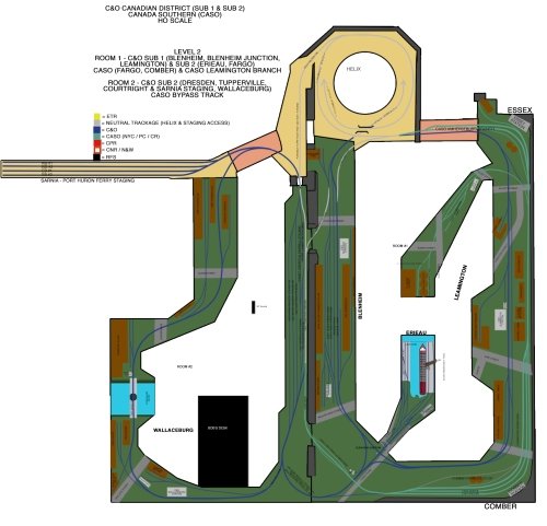
We’ll look at Level 2 in the next update on the blog, which will look at modelled locations for Blenheim, Blenheim Junction and Leamington on C&O Sub 1, Erieau, Blenheim Junction, Fargo and Wallaceburg on C&O Sub 2. CASO modelled locations on Level 2 include Fargo, Comber, Leamington and Essex. C&O staged locations include Darrell, Eberts, Ennett, Dresden, Tupperville, Port Lambton, Courtright, Sarnia and the Sarnia-Port Huron car ferry.


You must be logged in to post a comment.